
Page 33 - Build 165
P. 33
DESIGN
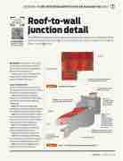
Roof-to-wall junction detail
The BRANZ helpline has been asked recently about how best to detail the tricky junction between the top edge of a monopitch roof and an adjacent wall above. Here is one suggestion.
2-storey
junction at top edge of monopitch roof and adjacent wall above
wall framing (insulation omitted for clarity)
upper wall underlay lapped over upturned roof underlay
Step 2 – self- adhesive
exible ashing membrane tted around junction and folded across the roof underlay turn-down
Step 1b – roof underlay turned down over lower wall underlay
lower wall underlay
RIGHT
DESIGN DETAIL FOR JUNCTION BETWEEN A MONOPITCH ROOF AND AN ADJACENT WALL ABOVE
BY ALIDE ELKINK,
FREELANCE TECHNICAL WRITER, WELLINGTON
WE CONTINUE the Build series on roof-to-wall junction details not included in Acceptable Solution E2/AS1 to the New Zealand Building Code clause E2 External moisture.
This detail occurs at the junction between the top edge of a monopitch roof and an adjacent wall above (see Figure 1).
Steps for installation
Figures 2–5 illustrate the steps of the construc- tion sequence for the detail with a sheet cladding material over a drained and vented cavity.
Step 1: Install roof and wall underlay over framing. Turn the roof underlay up under adjacent wall underlay (1a) and overlap the lower wall underlay (1b).
Step 2: Fit a self-adhesive, exible ashing membrane over the junction. Cut and fold a section of the membrane across the roof underlay turn-down.
Step 3: Install apron ashing over the roo ng with upstand over upper wall underlay. Apron ashing to have at least the minimum upstand height and roof cover required by E2/AS1.
Step 4: Lap an additional layer of wall underlay or x self-adhesive, exible ashing tape over the apron ashing upstand.
Step 5: Install cavity battens to lower wall.
Step 6: Install internal corner wall ashing over cavity battens on the lower wall. The corner ashing must end behind the barge ashing.
Step 7: Install lower wall cladding over cavity battens and then install fascia board.
fall single storey
Figure 1
Junction detail location.
Step 1a – roof underlay turned up under upper wall underlay
roo ng
purlin
wall framing (insulation omitted for clarity)
Figure 2
Steps 1–2 – Roof/wall junction construction sequence.
Build 165 — April/May 2018 — 31
